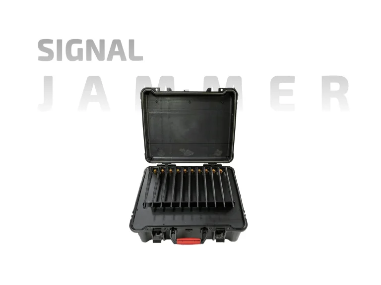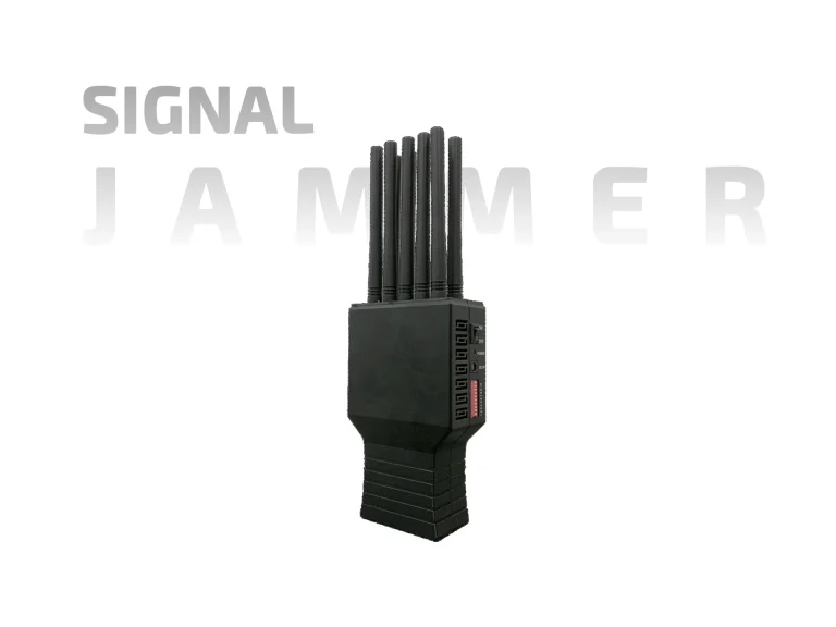
A vehicle-mounted signal jammer is not a trolley with an engine. The moment RF equipment is integrated into a moving platform, a new set of engineering constraints appears: vibration, electrical system interaction, antenna placement on a metal body, thermal management in a sealed cabin, and the difficulty of containing emissions from a platform that travels through uncontrolled space. These constraints are rarely discussed in product listings, yet they determine whether a vehicle-mounted system performs as intended—or becomes an expensive installation that cannot be used.
For the coverage principles that govern where vehicle-mounted emissions actually reach, see Signal Jammer Range: What Actually Determines It?.

What Makes Vehicle Integration Different
A fixed installation has stable power, stable temperature, and a known coverage boundary. A vehicle has none of these by default. The electrical system is shared with the engine, lighting, and safety electronics. The cabin temperature swings with weather and engine load. The platform moves, so the coverage boundary moves with it—often into areas where interference is neither intended nor lawful.
| Integration factor | Fixed installation | Vehicle-mounted platform |
|---|---|---|
| Power source | Dedicated circuit | Shared with vehicle electrical system |
| Thermal environment | Controlled room | Engine heat, solar load, sealed cabin |
| Vibration and shock | Minimal | Continuous road-induced stress |
| Antenna grounding | Designed ground plane | Vehicle body acts as irregular ground |
| Coverage boundary | Defined by site | Moves with the vehicle |
| Containment | Shielded room or fence | Difficult; emissions travel with platform |
The Power System Problem
Vehicle electrical systems were not designed to feed RF amplifiers. Alternator output, battery capacity, and wiring gauge all impose limits that are easy to exceed. A high-output jammer can overload the alternator, drain the battery, or trip protection circuits that also serve safety-critical systems. Integration therefore begins with an electrical audit, not with the RF hardware.
| Power consideration | Risk if ignored | Practical mitigation |
|---|---|---|
| Alternator capacity | Voltage sag, battery drain | Calculate continuous and peak load |
| Battery reserve | Inability to start engine | Isolate jammer from starting circuit |
| Wiring gauge and fusing | Overheating, fire risk | Size conductors for worst-case current |
| Grounding strategy | Noise, ground loops, RF instability | Single-point ground planning |
| Inverter or DC-DC conversion | Conversion losses, heat | Specify efficiency and thermal margin |
| Shutdown isolation | Parasitic drain when parked | Install a dedicated master disconnect |
Antenna Placement on a Metal Body
The vehicle body is a large, irregular conductor. It can act as a ground plane, a reflector, or a shield depending on where an antenna is mounted. Placement decisions that look convenient—roof racks, rear pillars, side panels—can create pattern distortion, nulls, and coupling between antennas. Authorized integrators treat antenna placement as a measured engineering task, not a mounting convenience.
| Mounting location | Typical effect | Verification needed |
|---|---|---|
| Roof center | Most uniform ground plane | Pattern measurement with vehicle present |
| Roof edge | Asymmetric pattern, possible nulls | Compare against center-mount data |
| Rear pillar | Body shadowing in forward direction | Directional coverage assessment |
| Side panel | Strong coupling to vehicle electronics | EMI and pattern testing |
| Bumper or low mount | Ground reflection and blockage | Height and clearance analysis |
| Multiple antennas | Mutual coupling and intermodulation | Spacing and isolation study |
Vibration, Shock, and Environmental Stress
A vehicle-mounted signal jammer experiences continuous vibration and occasional shock. Connectors loosen, solder joints crack, fans seize, and mounting hardware fatigues. Equipment that performs well on a bench may fail within months on a moving platform. Ruggedization is not cosmetic; it is a reliability requirement that affects connector choice, board mounting, and enclosure design.
| Stress source | Typical failure mode | Design response |
|---|---|---|
| Road vibration | Connector loosening, fastener fatigue | Thread-locking, strain relief, shock mounts |
| Thermal cycling | Solder joint cracking | Thermal expansion matching |
| Dust and moisture | Fan failure, corrosion | Sealed enclosures, filtered airflow |
| Engine heat soak | Derating, thermal shutdown | Heat shielding and airflow routing |
| Operator handling | Cable and connector damage | Ruggedized interfaces and cable management |
Containment Travels With the Vehicle
The most underappreciated challenge is containment. A fixed jammer emits into a known area. A vehicle-mounted jammer emits wherever the vehicle goes—past hospitals, airports, emergency routes, and populated areas. Authorized teams must plan routes, define operating boundaries, and establish shutdown procedures that account for the platform’s mobility. In many jurisdictions, this alone makes open-road operation unlawful regardless of the equipment’s design.
| Containment concern | Why vehicle mounting amplifies it | Planning response |
|---|---|---|
| Unintended receiver exposure | Emissions move through public space | Route and boundary planning |
| Emergency service interference | Vehicle may pass near critical infrastructure | Pre-mapped exclusion zones |
| GNSS disruption | Affects the vehicle’s own navigation and nearby users | Timing and location awareness |
| Operator situational awareness | Driver and operator roles conflict | Dedicated operator, not the driver |
| Rapid shutdown need | Vehicle may enter restricted areas | Accessible kill switch and drill |
A Deployment Framework for Authorized Teams
Integration should follow a defined sequence: electrical audit, thermal assessment, antenna placement study, vibration hardening, containment planning, and operator training. Each step produces documentation that supports later compliance review. Skipping any step shifts risk to the field, where correction is far more expensive.
The Takeaway
A vehicle-mounted signal jammer is an integration project, not a product purchase. Power, thermal, antenna, vibration, and containment challenges all intensify when RF equipment is placed on a moving platform. Authorized teams that treat these challenges as engineering requirements—and that document each decision—will build systems that work as intended. Those that focus on output wattage alone will discover the platform’s limits the hard way.