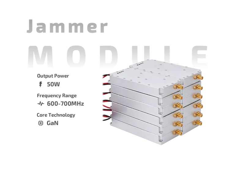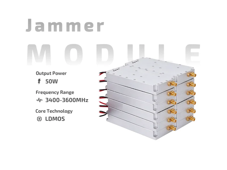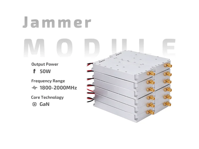
A 5.8GHz 50W drone jammer module sits at the intersection of two engineering realities. The 5.8GHz band is short in wavelength, which makes antennas compact and beams tight. Fifty watts is a substantial RF output for this band, which makes heat and linearity the dominant design constraints. Together, they create a module that rewards careful system design and punishes improvisation.
This guide treats the 5.8GHz 50W configuration as a specific engineering case rather than a generic power class. For power-chain fundamentals that apply across this output range, see 30W drone jammer module power supply.

Why 5.8GHz behaves differently
The 5.8GHz band is widely associated with drone video and telemetry links, which makes it a relevant frequency for counter-drone system designers. Physically, the band presents several characteristics that shape module design:
-
Shorter wavelength: At 5.8GHz the wavelength is roughly 5.2 cm, compared with about 12.5 cm at 2.4GHz. This allows smaller antennas and more compact arrays, but also narrower beamwidths for a given aperture.
-
Higher free-space loss: Path loss increases with frequency. A 5.8GHz link experiences roughly 7.6 dB more free-space loss than a 2.4GHz link over the same distance. This affects how much link margin a 50W output actually provides.
-
Greater sensitivity to blockage: Higher frequencies diffract less around obstacles, so line-of-sight conditions matter more.
-
Compact filtering: Filters at 5.8GHz can be physically small, but achieving high rejection in a compact package requires careful design.
These factors mean a 5.8GHz 50W module cannot be evaluated with the same assumptions used for lower-frequency modules. The band’s propagation behavior changes the effective coverage, and the compact antenna geometry changes the integration approach.
What 50W means at 5.8GHz
At 5.8GHz, 50W corresponds to approximately 47 dBm at the module output. The practical significance depends on the antenna system and the target link. Because free-space loss is higher at 5.8GHz, the same output power yields less received power at a given distance than at 2.4GHz. The module’s output must therefore be assessed as part of the full link budget, not in isolation.
| Parameter | Indicative value at 5.8GHz | Engineering note |
|---|---|---|
| Module output | ~47 dBm (50W) | Confirm per-band or total rating |
| Free-space loss vs 2.4GHz | +7.6 dB | Higher frequency loses more over distance |
| Antenna gain potential | Higher for same aperture | Shorter wavelength allows more compact high-gain designs |
| Beamwidth for typical antenna | Narrower | Placement and aiming become more critical |
| Amplifier efficiency | Often lower than at lower bands | Heat per watt of RF output can be higher |
The last point deserves emphasis. Power amplifiers at 5.8GHz often operate at lower efficiency than their lower-frequency counterparts. A 50W module at 5.8GHz may draw more DC input power per watt of RF output than a comparable 50W module at a lower band. This directly affects thermal design and power supply sizing.
Thermal design is the binding constraint
At 50W and 5.8GHz, heat is not a secondary concern. It is the primary design driver. The amplifier stage concentrates dissipation in a small area, and the compact enclosure typical of 5.8GHz modules offers limited surface area for heat rejection.
| Thermal approach | Suitability for 5.8GHz 50W | Trade-offs |
|---|---|---|
| Passive heatsink only | Short duty or low ambient | Simple but limited continuous capability |
| Heatsink with forced air | Good for many installations | Adds fan, filter, and maintenance item |
| Conduction to chassis | Effective in vehicle or shelter mounts | Requires careful thermal interface design |
| Liquid-assisted cooling | High-duty or enclosed systems | Complexity and cost increase significantly |
| Phase-change or heat-pipe | Compact high-density designs | Specialized, less common in field equipment |
A 5.8GHz 50W module specified for continuous operation should be evaluated with its actual cooling solution, not a bench heatsink. Derating curves should be requested at realistic ambient temperatures, and the thermal path from amplifier to ambient should be documented.
Antenna and RF chain considerations
The compact wavelength at 5.8GHz is both an advantage and a risk. Smaller antennas are easier to mount, but narrow beamwidths mean that aiming errors have a larger effect. In a multi-antenna installation, physical spacing between antennas may be small in absolute terms, which can affect isolation.
| RF chain element | 5.8GHz-specific consideration | Integration impact |
|---|---|---|
| Antenna | Compact, higher gain for same size | Aiming and mounting precision matter more |
| Cable | Lower loss per metre than lower bands | Connector quality becomes relatively more important |
| Connectors | Standard SMA often used | Verify power rating and torque spec |
| Filtering | Compact but high-rejection design needed | Poor filtering can affect adjacent bands |
| Isolation | Shorter wavelength allows close spacing | Verify inter-antenna isolation empirically |
Cable loss at 5.8GHz is generally lower per metre than at lower frequencies, but connector and adapter losses can dominate in short runs. Minimizing adapters and using quality connectors is often more effective than upgrading cable.
Matching the module to the mission
| Mission profile | 5.8GHz 50W suitability | Design focus |
|---|---|---|
| Portable short-duration kit | Possible with duty limits | Battery and thermal management dominate |
| Vehicle-mounted node | Strong fit | Vehicle power and airflow support continuous use |
| Fixed site with directional antenna | Strong fit | Antenna gain and aiming precision are key |
| Multi-band system with 5.8GHz chain | Good as a dedicated band module | Confirm isolation from adjacent bands |
| Enclosed shelter system | Workable with active cooling | Thermal design must be validated in enclosure |
| Manpack long-duration | Challenging | Weight and heat constrain continuous operation |
The pattern is consistent: 5.8GHz 50W favours installations with stable power, adequate airflow, and precise antenna mounting. Portable applications are possible but usually require duty-cycle discipline.
Integration checkpoints
-
Confirm whether 50W is total output or output at the antenna connector.
-
Obtain the derating curve at the expected ambient temperature.
-
Verify amplifier efficiency and calculate DC input power.
-
Select a cooling solution rated for continuous operation, not bench testing.
-
Confirm antenna gain, beamwidth, and mounting tolerances.
-
Measure connector and adapter losses in the actual RF chain.
-
Check isolation from other bands or antennas in the system.
-
Validate VSWR protection and over-temperature behaviour.
-
Confirm the control interface supports required monitoring.
-
Verify the band and output power are authorized in the target jurisdiction.
Bottom line
A 5.8GHz 50W drone jammer module is a compact, high-power RF building block whose performance is shaped by band physics and thermal reality. The shorter wavelength enables compact high-gain antennas but demands precise aiming. The 50W output provides meaningful link margin but requires serious cooling and power planning. Design the thermal path, verify the RF chain, and validate at realistic ambient conditions—then the module will deliver what the datasheet promises.