October 22, 2026
50W LoRa Drone Jammer Module: Design & Compliance
A practical industry overview of 50W LoRa drone jammer modules: RF design, thermal management, EMC, compliance, and authorized deployment.

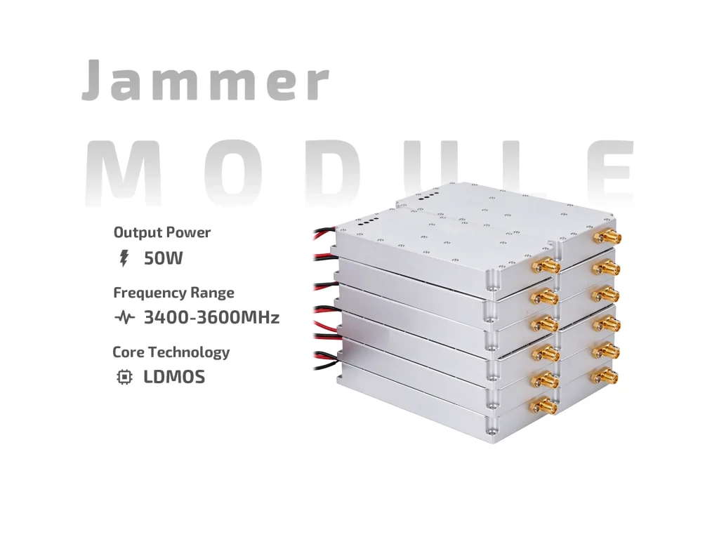
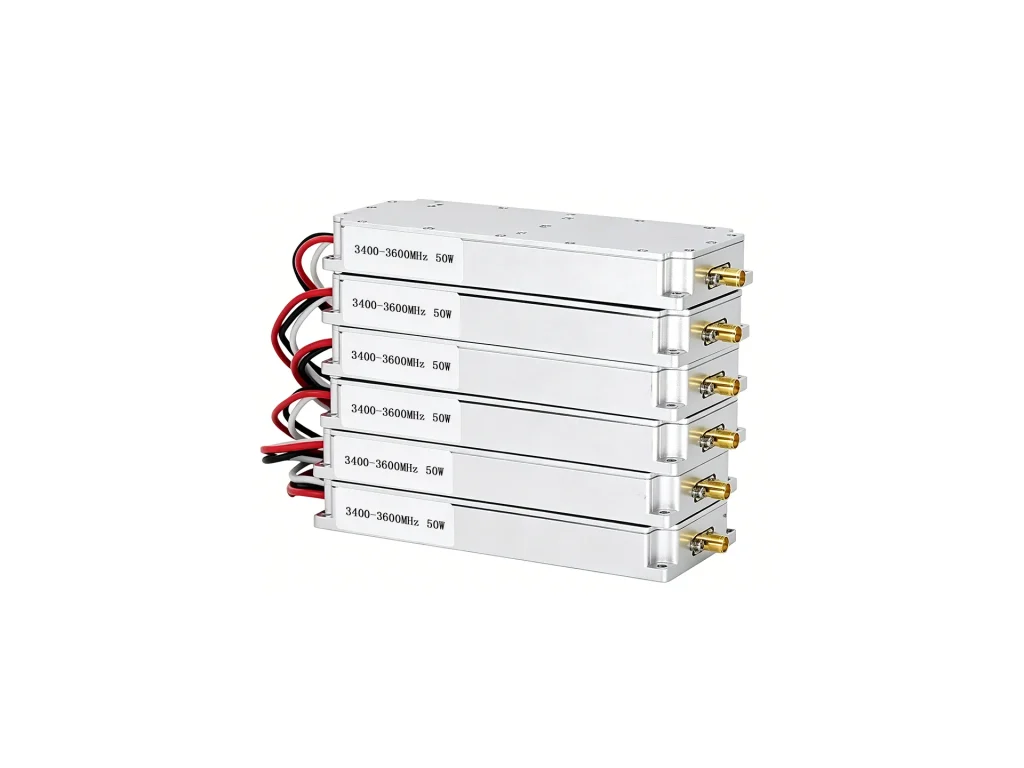
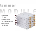
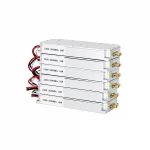
JM3436L50 50W anti-drone module covers 3400–3600MHz, 28V, 47±1dBm, 270kHz scan, SMA female, 117×58×18mm, 300g. Custom options available.
The JM3436L50 is a 50W Anti-Drone Module for 3400–3600MHz countermeasure and video-link shielding. It combines a GaN/LDMOS RF chain, an internal noise source, and protection circuits in a compact metal case. Integrators use it as a focused RF block, not a complete detection system. It needs DC power, an antenna, and a thermal path.

The module delivers 47±1dBm, roughly 50W, across 3.4–3.6GHz. That band carries many drone video and telemetry links. Raising the noise floor in this band can disrupt those links in the antenna sector. The default analog scan speed is 270kHz. Custom scan rates from 100kHz to 500kHz can be ordered. Match the antenna to the band and check VSWR before full power.
A built-in high-speed noise modulation source is standard. This simplifies field wiring: feed DC, connect the SMA female port, and manage heat. For different waveforms, the source can be customized to VCO, DDS, or SDR. Ask for a sample test when changing the source. Cable loss at 3.5GHz is real, so keep coax short and low-loss.
Nominal voltage is 28V, with a 24–28V operating range. Current draw is ≤3.2–4.5A at 50W output. LEDs show power, overvoltage, and overtemperature. These indicators help during bench setup and fault finding. Use a supply with headroom for transients; a 50W RF stage is not a light load.
The case is 117×58×18mm and weighs about 300g. It fits tight ground or airborne enclosures. At 50W, heat is the main limit. Mount it to metal with good contact, apply thermal interface material, and keep air moving over the case. Rated operating temperature is -20 to +65°C under normal operation.
Frequency range, scan speed, signal source, connector, and dimensions can be customized. If your enclosure has a fixed footprint, request a drawing before tooling. Custom RF settings should be verified on a sample. Changes to band or source may affect lead time and test scope. Plan RF testing before full production.
Keep the antenna away from sensitive receivers. Use short low-loss coax and confirm VSWR before applying full power. Start on the bench at reduced duty cycle, then move to field testing. Check the LED status during warm-up. The JM3436L50 suits anti-drone and signal-shielding roles, including video transmission disruption. Use only where local rules allow.
Typical uses include fixed-site counter-drone systems, mobile patrol units, and video-link shielding. The 3400–3600MHz range is narrow enough for directional antennas and broad enough for practical alignment. Integrators can combine it with detection and control layers. The module is an RF effector, not a standalone security system.
Use a directional antenna for focused coverage. A wideband panel or horn can cover the full band, but gain and beamwidth trade off. Aim the sector away from friendly receivers. Keep the antenna clear of metal edges. Test at the intended mounting height; ground reflections change the pattern.
Use a stable 28V supply with margin for peak current. Protect the DC line with a fuse or breaker. Keep power and RF cables separated where possible. Strain-relieve the SMA connection. Label the overvoltage and overtemperature LEDs in your enclosure so field checks are quick.
The Anti-Drone Module is rated for normal operation at -20 to +65°C. Long high-power runs need a defined duty cycle and airflow. Monitor case temperature during initial testing. If the overtemperature LED trips, improve the thermal path before increasing power or run time. This protects the RF chain and extends service life.
The JM3436L50 packs 50W output, 3400–3600MHz coverage, and a 117×58×18mm housing. It gives integrators a practical 50W Anti-Drone Module with flexible signal-source options and clear status indicators.
| Parameter | Specification | Notes |
| Frequency band | 3400–3600 MHz, customizable | 3.4–3.6 GHz |
| Output power | 47±1 dBm, 50 W | Typical |
| Operating voltage | 28 V, 24–28 V range | Nominal 28 V |
| Operating current | ≤3.2–4.5 A at 50 W output | Depends on voltage |
| Input signal source | Built-in high-speed noise modulation source, VCO/DDS/SDR optional | Custom |
| Dimensions | 117×58×18 mm, or customized | L×W×H |
| Analog scan speed | 270 kHz, 100–500 kHz customizable | Analog |
| Operating temperature | -20 to +65 °C | Normal operation |
| Connector | SMA female | RF output |
| LED indicators | Power switch, overvoltage, overtemperature | Status |
| Weight | 300 g | Approx. |
| Module customization | Supported: frequency, scan speed, source, connector, size | Confirm by sample |
A practical industry overview of 50W LoRa drone jammer modules: RF design, thermal management, EMC, compliance, and authorized deployment.
Explore 5.8GHz 50W drone jammer module design: band physics, EIRP, thermal challenges, antenna matching and integration checkpoints.
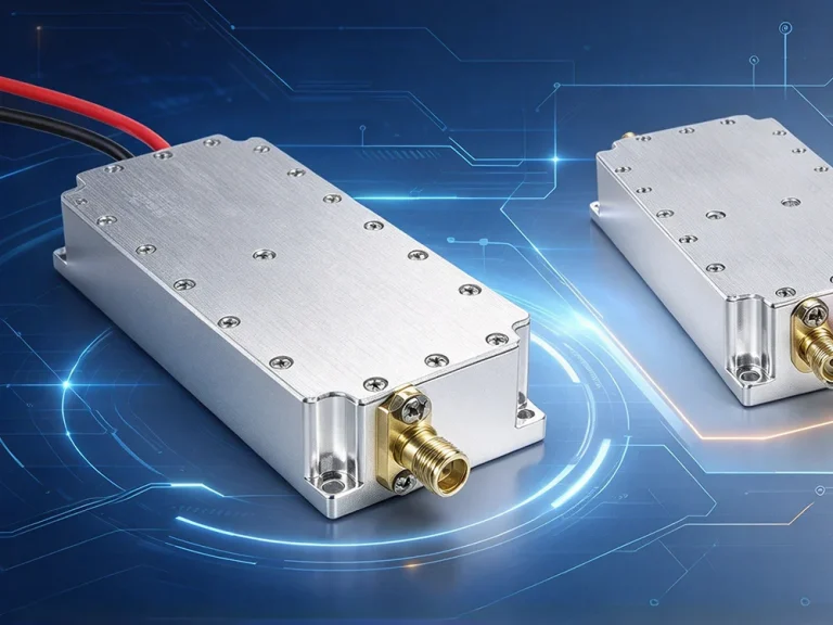
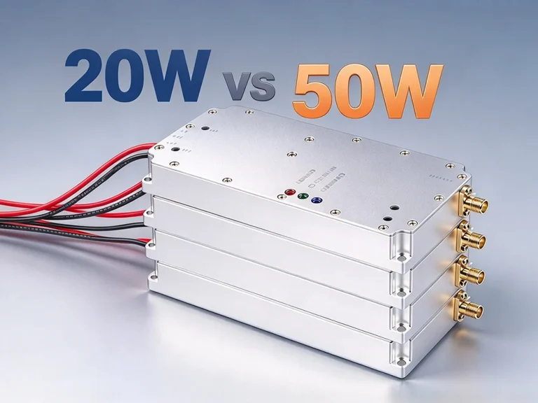
Compare 20W vs 50W drone jammer modules by range, heat, power and deployment. Choose the right counter-drone module with practical tips.