October 22, 2026
100W GaN Drone Jammer Module: Does GaN Deliver?
GaN promises efficiency and power density in 100W drone jammer modules. Here is where the gains are real, where they shrink, and what to verify.


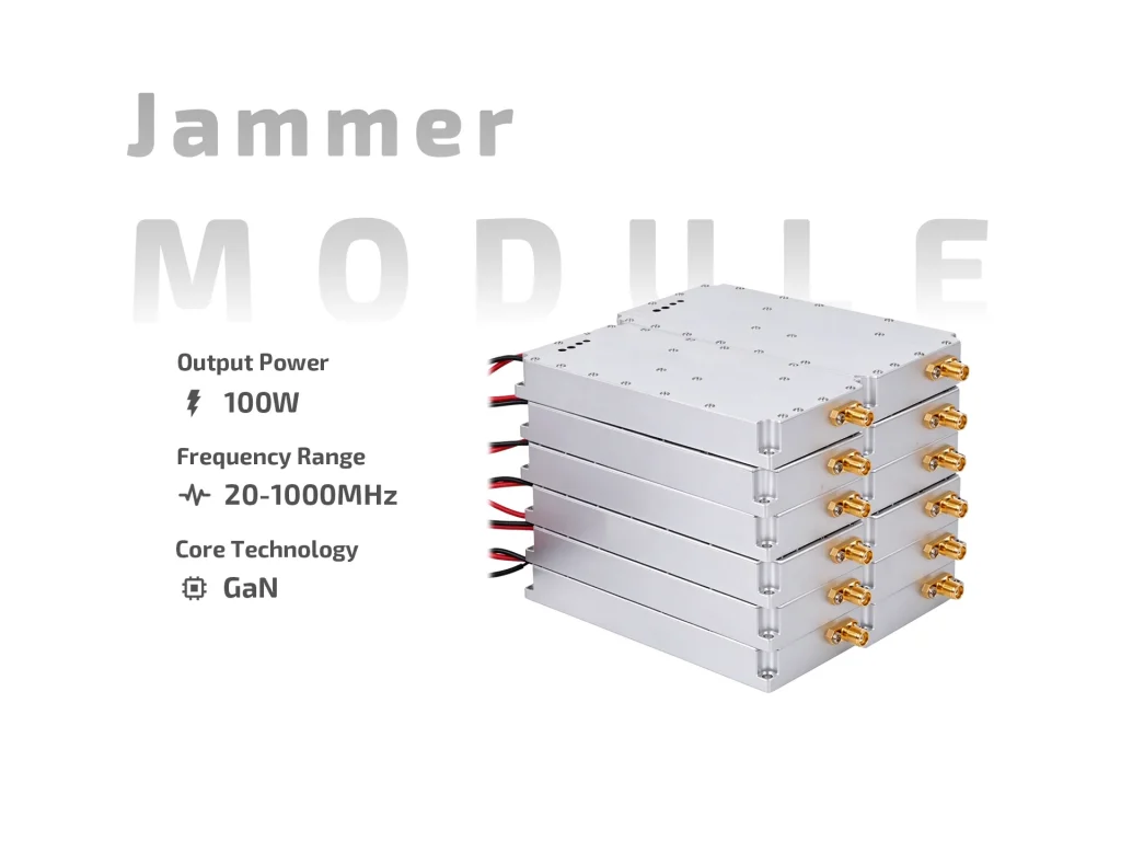
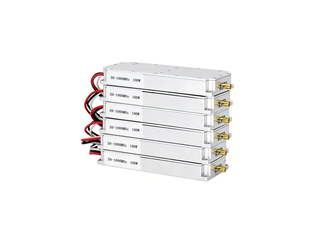
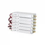
JM0210G100 100W GaN drone jammer module: 20–1000MHz custom segment, DC24–29V, 12A max, ≥40% efficiency, SMA female, built-in sweep source.
If your counter-drone product needs a lower-band RF engine, the JM0210G100 is worth a look. It is a 100W GaN drone jammer module built for a custom segment inside 20–1000MHz. You choose the segment; the factory tunes the module to it. That approach suits integrators who know their target link and do not want to pay for spectrum they will never use. The module includes a built-in high-speed sweep source, runs from DC24–29V, and uses an SMA female RF port.

The 20–1000MHz range is wide. Do not read it as one module covering everything at once. The order defines the working segment, and the internal sweep source is set for that segment. Put the expected centre frequency and bandwidth in the inquiry. Check nearby transmitters before you finalise the segment. A narrow, well-chosen slice often filters more easily than a broad one. GaN output devices give the 100W stage thermal headroom, and efficiency is at least 40%.
Input is 24–29V DC. Maximum current is 12.0A, so use short, thick leads and a fuse rated with margin. The switch line is simple: +5V or floating turns the module on; grounding turns it off. That works with a relay, an open-collector driver, or a manual switch. Add reverse-polarity protection in the host. Check the control polarity before the first power-up.
Output VSWR should be 2.0 or lower. That is a system target, not just a module number. Use an antenna that covers your ordered segment and holds a good match across it. Keep the coax short and shielded. The SMA female port is fine for short runs; avoid adapters where possible. The data sheet does not list an internal VSWR protection device, so a matched load and host-side protection matter.
The case measures 158.5×93.5×24mm and weighs 0.55kg. Mount the base to metal, use thermal compound, and allow air movement. Do not hang the unit from the coax. Leave room for the SMA connector and bend radius. The 24mm height helps in thin housings, but heat still needs a path to the outside. Four screws and a thin thermal pad are a good start.
The 100W figure is not free heat. At 40% efficiency, a large share of DC input leaves as heat. Use a duty cycle that matches the housing. In sealed boxes, bring heat to external metal. A small fan inside a closed case only moves warm air. If the unit runs hot, reduce duty or improve the mounting path. Measure the base temperature, not just the air.
Antenna gain and height often do more than extra power. A lower-band antenna can be large, so plan the mount early. Check for strong nearby signals that could desensitise the receive side of your system. Keep people away from the antenna front. RF exposure depends on gain, distance, and duty cycle. A site check is more useful than a single wattage claim.
Test into a dummy load before connecting the antenna. Log current at 24V and 29V. Feel the mounting face after a short run. Confirm the sweep source is working over the ordered segment. Keep DC and control lines away from the RF path. Use only where drone-link disruption is authorised. The drone jammer module is a building block; the host still needs an enclosure, antenna, power protection, cooling, and legal approval.
Ask for the exact segment, connector orientation, and test data. Confirm whether the sweep source is fixed or adjustable for your order. For multi-band products, plan separate modules and a proper combiner. Do not parallel outputs without RF design support. A clear order specification avoids surprises. The JM0210G100 is a focused lower-band module, not a finished jammer.
The 100W GaN drone jammer module is not a finished consumer jammer. It has no battery, display, or antenna. It does not decide which links to target. Treat it as one RF module inside a larger authorised product. That view keeps expectations and legal checks in the right place.
| Parameter | Specification | Notes |
| Frequency | 20–1000 MHz | Custom segment inside this range; order defines the working band |
| Output Power | 100 W | GaN output stage |
| Output VSWR | ≤2.0 | Keep antenna and coax matched |
| Operating Voltage | DC24–29 V | Regulated supply recommended |
| Max Current | 12.0 A | Allow wiring and fuse headroom |
| Efficiency | ≥40% | Thermal design still required |
| Switch Control | +5V or floating = ON; ground = OFF | Relay or open-collector drive possible |
| Output Connector | SMA female | Short shielded coax |
| Interference Source | Built-in high-speed sweep source | Set for the ordered segment |
| Dimensions | 158.5×93.5×24 mm | Mount base to metal |
| Weight | 0.55 kg | Support the housing properly |
GaN promises efficiency and power density in 100W drone jammer modules. Here is where the gains are real, where they shrink, and what to verify.
A procurement-focused review of 100W FPV jammer modules: where the extra power helps, where it costs, and what to validate before purchase.
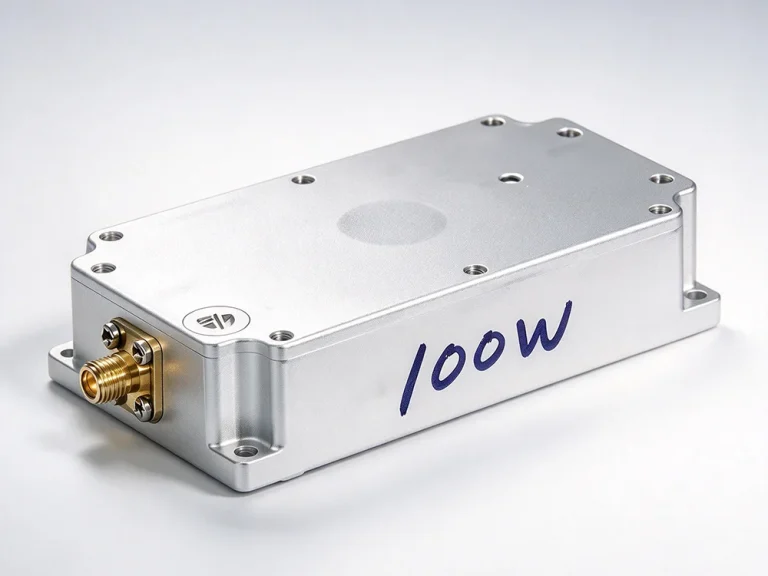
Comparing 80W vs 100W drone jammer module: real thermal gaps, efficiency trade-offs, bandwidth costs, and when the extra 20W is worth it.