October 22, 2026
100W GaN Drone Jammer Module: Does GaN Deliver?
GaN promises efficiency and power density in 100W drone jammer modules. Here is where the gains are real, where they shrink, and what to verify.


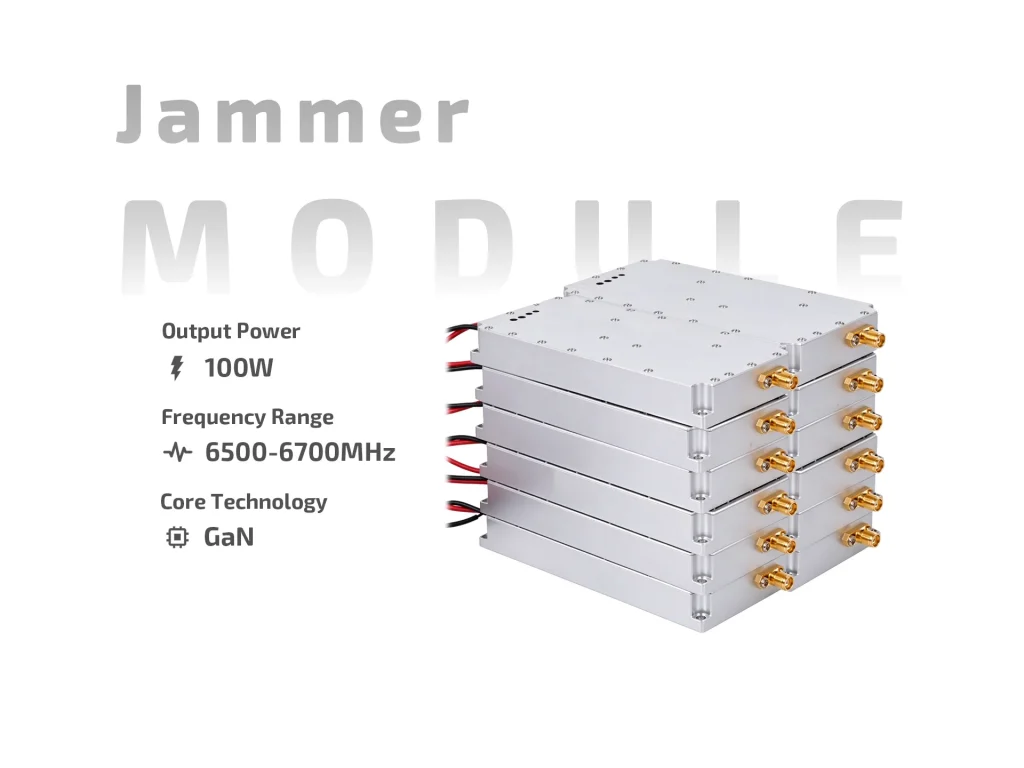
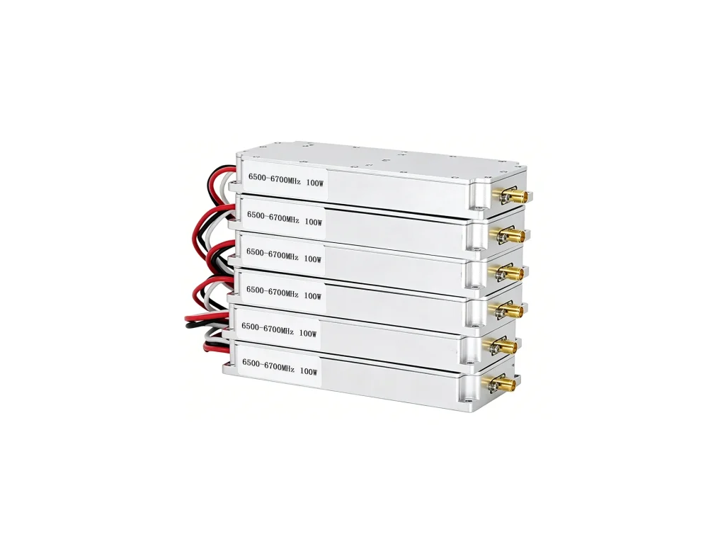

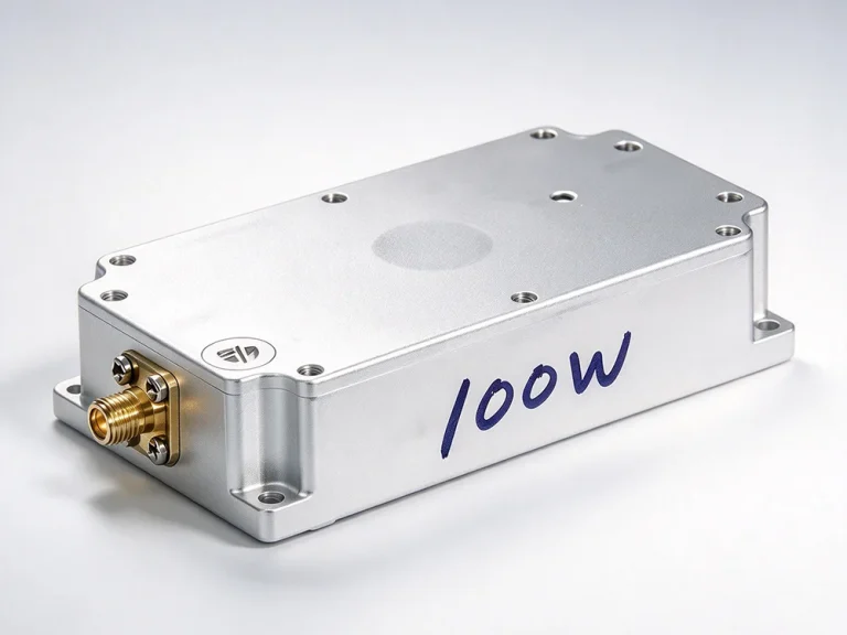
JM6567G100 100W GaN jammer module: 6500–6700MHz, DC24–29V, 12A max, ≥40% efficiency, built-in sweep source and VSWR protection.
The JM6567G100 is a 100W GaN Jammer Module for 6500–6700MHz. It packs a GaN output stage, a built-in high-speed sweep source and protection into a 168.5×84.5×23mm case. It is an integrated analog jamming module, not a finished product. You supply DC power, switching logic and a matched antenna or load.

The module covers 6500–6700MHz with 100W output and output VSWR ≤2.0. The internal sweep source saves an external generator and extra cabling. SMA female output is standard. At 6.5GHz, coax loss and connector quality matter. Use short, rated cable. Check the load before full power. A poor match reflects energy and raises heat.
Input is DC24–29V. Maximum current is 12.0A, and efficiency is ≥40%. At 100W, heat is expected. Mount the 0.55kg case on a flat metal plate with thermal compound. Provide airflow or a cold plate. Use thick, short DC leads. Make sure the supply holds voltage at 12A. Check voltage at the module terminals, not only at the PSU. If voltage sags, output and stability can drop.
A +5V or floating control turns the module on. Ground turns it off. The input is simple and can be driven by a relay, MCU or manual switch. Built-in absorptive VSWR protection helps during mismatch, but it is not a substitute for a proper load. Test the antenna and cable first. Raise power slowly and watch current and case temperature.
Keep the module away from sensitive receivers. Use shielded RF paths. Separate DC and control lines from the RF output. The metal case is compact, but it still needs a solid ground and clear airflow. Do not hot-plug RF connectors. Use strain relief on DC leads. Leave space for connectors and cable bends.
Typical uses include anti-drone RF suppression, protected-site testing, link denial and fixed or mobile integration. The 100W GaN Jammer Module can drive suitable antennas, but range depends on antenna gain, beamwidth, cable loss and site rules. Confirm local RF regulations, filtering and safety before deployment.
Confirm the band plan, control polarity and supply headroom. Check that the antenna covers 6500–6700MHz and handles 100W. Start with a known load or attenuator. Apply DC24–29V within the 12.0A limit. Confirm switching. Then raise drive and record output at several points. Stop if current jumps or output falls. Repeat after final assembly.
Do not rely on the case alone. A thin, even layer of thermal compound on a flat sink works better than a thick pad. In a sealed box, bring air over the fins or use a cold plate. Check case temperature after 10–15 minutes at full power. A steady input with rising current is a warning sign. Let the module cool before changing connectors.
At 6.5GHz, small cable and connector faults show up fast. Use coax rated for the band and power. Inspect SMA pins and threads. Tighten gently and avoid unnecessary adapters. Test cable loss before connecting the module. Keep spare jumpers and label each RF path.
In a rack or mobile case, vibration can loosen connectors. Use cable ties and service loops. Keep the heatsink clear. Label DC and control leads. If the drone jammer module shares an enclosure with receivers, use distance and shielding. Check current draw at each site.
The JM6567G100 is a practical 100W GaN Jammer Module for 6500–6700MHz work. It gives integrators a tested RF block with an internal sweep source and simple switching. Matching, cooling and supply design matter as much as the power rating. Treat it as a building block, not a plug-and-play consumer device.
| Parameter | Specification | Notes |
| Operating frequency | 6500–6700 MHz | C-band coverage |
| Output power | 100 W | GaN output stage |
| Output VSWR | ≤2.0 | Keep load matched |
| Operating voltage | DC 24–29 V | Check supply headroom |
| Maximum operating current | 12.0 A | At rated operation |
| Efficiency | ≥40% | Heat removal needed |
| Switch control | +5 V or floating = ON; ground = OFF | Simple logic input |
| Output connector | SMA female | Standard RF interface |
| Interference source | Built-in high-speed sweep source | No external generator |
| VSWR protection | Built-in absorptive VSWR protection | Helps with mismatch |
| Dimensions | 168.5 × 84.5 × 23 mm | L × W × H |
| Weight | 0.55 kg | Module only |
GaN promises efficiency and power density in 100W drone jammer modules. Here is where the gains are real, where they shrink, and what to verify.
A procurement-focused review of 100W FPV jammer modules: where the extra power helps, where it costs, and what to validate before purchase.
Comparing 80W vs 100W drone jammer module: real thermal gaps, efficiency trade-offs, bandwidth costs, and when the extra 20W is worth it.