October 22, 2026
1.2GHz 60W Anti-Drone Module: Buyer’s Checklist
A procurement-focused look at 1.2GHz 60W anti-drone modules: band planning, thermal limits, interfaces, test data, and authorized deployment.
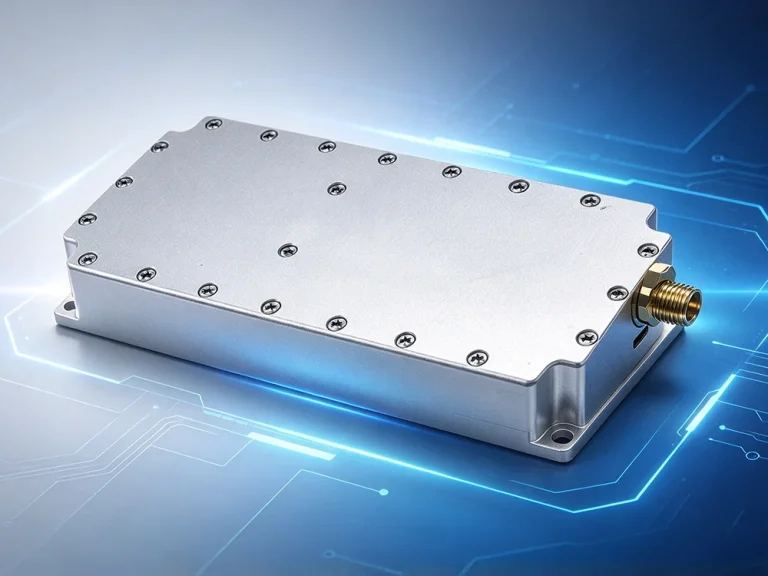

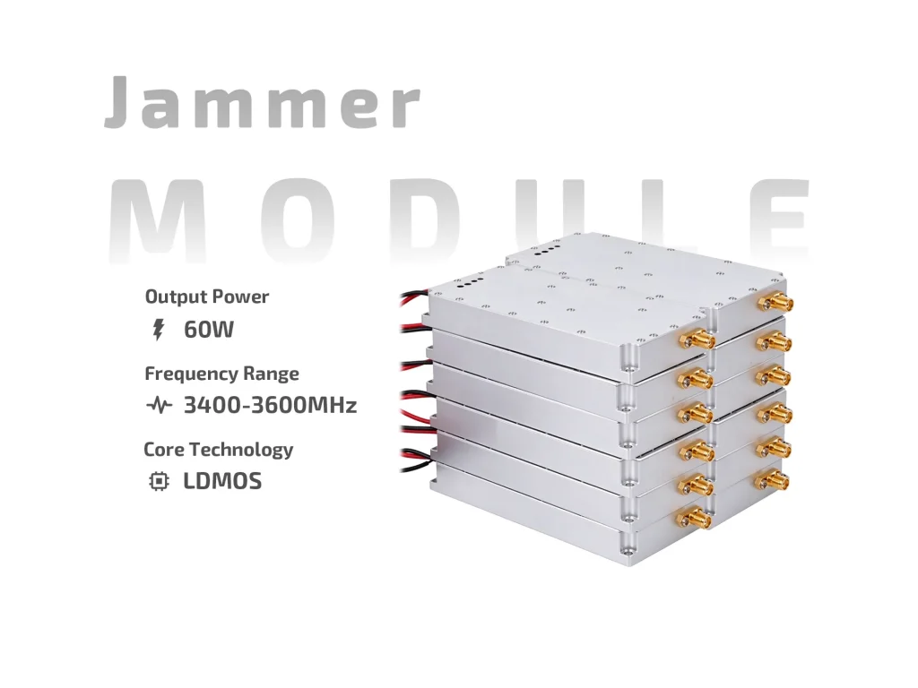
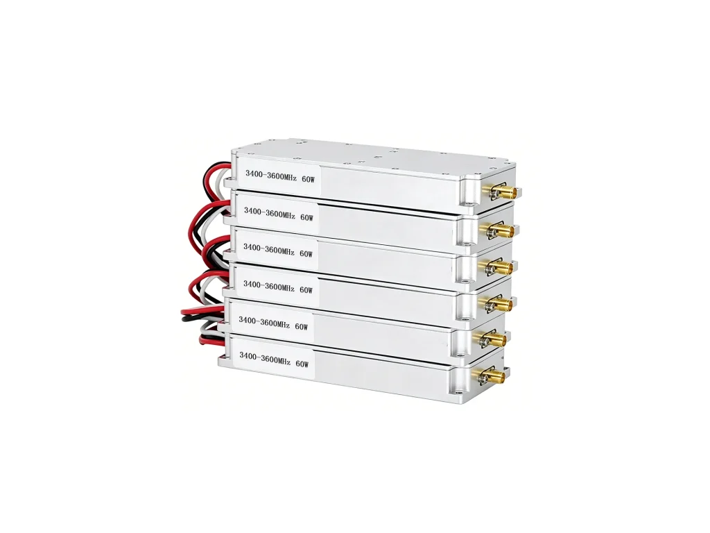
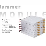
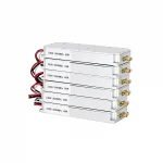
JM3436L60 60W LDMOS anti-drone module covers 3400–3600MHz with 12–14V DC, 12A max, ≥40% efficiency, built-in sweep source, SMA-F, 138×50.5×17mm.
JM3436L60 is a 60W LDMOS Anti-Drone Module built for 3400–3600 MHz countermeasure links. It combines a solid-state RF chain with an internal high-speed sweep source, so integrators can add DC power, control, and an antenna without designing a separate signal generator. The module is aimed at fixed sites, vehicle mounts, and portable housings where space and heat are tight.

LDMOS gives a good balance between gain, ruggedness, and cost in the 3.4–3.6 GHz range. At 60W, the module can support short- to medium-range jamming tasks while keeping current draw within a 12V–14V platform. Efficiency is listed at ≥40%, which matters when the enclosure is sealed and airflow is limited. The output stage is protected against poor load conditions up to VSWR 2.0, but a clean antenna match still helps stability and service life.
The built-in high-speed sweep source saves board space and removes external cabling. It is not a full SDR; treat it as a compact interference engine for repeatable wideband coverage. The SMA female output is standard and works with common test loads and directional couplers. Keep the RF path short and use quality coax. If the module sits near a high-power transmitter, add filtering and shielding rather than relying on the housing alone.
Run the unit from a regulated DC12V–14V supply that can deliver at least 12A continuously. The switch control is simple: +5V or floating means on, grounding means off. That suits remote enable lines and fail-safe shutdown. Use a clean control ground and avoid long unshielded wires near the RF output. During bench tests, current-limited supplies are safer for first power-up.
At 138 × 50.5 × 17 mm and 0.22 kg, JM3436L60 fits compact housings and small turret mounts. Use thermal pads or paste to couple the base to a metal plate; do not rely on convection through the case. Leave room for SMA torque and cable bend radius. Mounting hardware should not distort the lid or press on internal boards.
Treat the anti-drone module as one RF block, not a complete jammer. Pair it with a suitable antenna, DC protection, and thermal design. For multi-module racks, separate DC feeds and sequence power to limit inrush. Check the output with a coupler and attenuator before connecting an antenna. Enclosures should allow airflow or external heatsinking, because 60W class devices concentrate heat in a small area.
Start with a dummy load and measure current, output power, and temperature rise. Sweep the band to confirm no unexpected dropouts. In the field, keep the antenna matched and inspect connectors after transport. Use short duty cycles when airflow is poor. The 3.4–3.6 GHz band is popular for broadband links, so coordinate frequency use and follow local rules before transmitting.
Thermal behavior deserves attention. The case is small, so the module will reach steady temperature quickly. A metal chassis with a flat mating surface works better than open air. If you place it in a sealed box, derate output or add a fan. Current draw can rise at lower supply voltage, so set the bench supply to 13.8V for realistic vehicle tests and watch the meter during sweep. Keep the control line clean; a floating input turns the unit on, which may surprise a technician during wiring. Label the harness clearly and pull the control line to ground for a safe default. RF connectors should be torqued to the antenna maker’s value, not over-tightened. After the first hour, check connector temperature and current again. Small changes often show a mismatch before damage occurs.
JM3436L60 is a practical 60W LDMOS Anti-Drone Module for teams that need a compact 3.4–3.6 GHz RF source with simple switching. It is best used with careful thermal design, a matched antenna, and realistic duty-cycle expectations. For volume builds, request a test report and confirm connector and control wiring before production.
| Parameter | Specification | Notes |
| Operating Frequency | 3400–3600 MHz | Covers the full 3.4–3.6 GHz band |
| Output Power | 60 W | Typical output at rated supply |
| Output VSWR | ≤2.0 | Keep antenna match within this limit |
| Operating Voltage | DC 12–14 V | Regulated supply recommended |
| Max Operating Current | 12 A | Size wiring and protection for continuous draw |
| Efficiency | ≥40% | Thermal design still required |
| Switch Control | +5 V or floating = ON | Ground = OFF |
| Output Connector | SMA female | Use quality coax and correct torque |
| Internal Sweep Source | High-speed sweep | No external signal generator needed |
| Dimensions | 138 × 50.5 × 17 mm | Allow clearance for SMA and cables |
| Weight | 0.22 kg | Compact housing support |
A procurement-focused look at 1.2GHz 60W anti-drone modules: band planning, thermal limits, interfaces, test data, and authorized deployment.
Sizing a 60W jammer module heatsink depends on efficiency, duty cycle, airflow, ambient, and enclosure. Use a thermal budget, not a wattage rule.

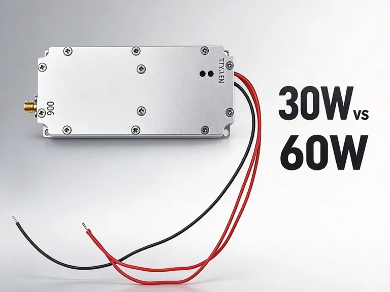
Compare 30W vs 60W drone jammer module by deployment scenario, thermal load, power budget and lifecycle cost. Choose the right tier.