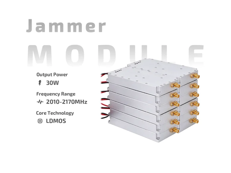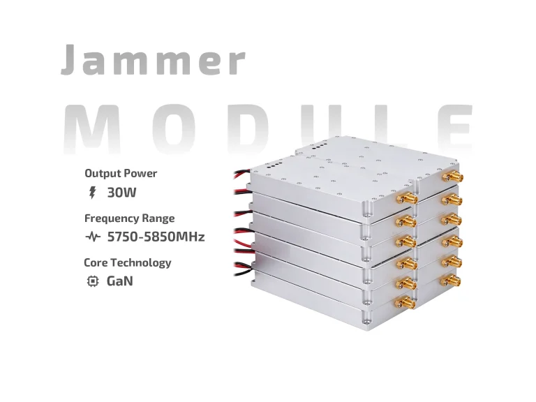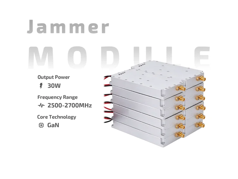
Most integration problems with a 30W drone jammer module do not start in the RF section. They start in the power chain. A module that performs perfectly on a bench supply can brown out, overheat, or trip protection the moment it is connected to a battery pack, a long cable run, or a shared vehicle bus.
This article treats the power supply as a design chain rather than a single component choice. For a wider view of how this power tier compares with the next one up, see 30W vs 60W Drone Jammer Module: Key Differences.

Start with the chain, not the wattage
Power for a 30W module passes through several stages: source, protection, conversion, distribution, and the module itself. Each stage introduces loss and each stage can become the weakest link.
A useful way to think about it: the module’s 30W figure describes RF output, not electrical input. The DC input is always higher because amplifiers are not perfectly efficient, and because control electronics, fans, and monitoring draw their own current. Sizing a supply from the 30W label alone is the most common cause of unstable installations.
A simple power-budget walkthrough
The calculation follows a fixed order:
-
Confirm RF output per band and total output.
-
Apply an amplifier efficiency assumption from the datasheet.
-
Add control, monitoring, and cooling loads.
-
Add margin for cable loss, conversion loss, and aging.
-
Compare the result against the supply’s continuous rating at the actual ambient temperature.
The example below is indicative only. Real figures must come from the module datasheet.
| Budget item | Indicative value | Comment |
|---|---|---|
| RF output (total) | 30 W | Confirm whether this is per band or total |
| Amplifier efficiency assumption | 35% | Datasheet value takes priority |
| Estimated DC draw for RF stage | ~86 W | 30 W ÷ 0.35 |
| Control and monitoring | 3–8 W | Depends on interface board and display |
| Cooling (if active) | 2–10 W | Fans or pump, if used |
| Subtotal before margin | ~91–104 W | Sum of the above |
| Recommended supply headroom | +25–30% | Covers inrush, cable loss, aging |
| Planning figure | ~115–135 W | Use as a starting point only |
Treat this as a planning exercise, not a specification. A module with better efficiency or a lower-duty profile will land lower; a multi-band unit or one with heavy monitoring may land higher.
Supply architecture options
| Architecture | Typical use | Strengths | Cautions |
|---|---|---|---|
| Bench or lab PSU | Evaluation and testing | Adjustable, current-limited, easy to monitor | Not representative of field behavior |
| 12V battery with DC-DC | Portable and manpack kits | Widely available, familiar | Higher current means thicker cable and more loss |
| 24V battery or bus | Vehicle and shelter systems | Lower current for the same power | Needs compatible conversion for control boards |
| Mains PSU with converter | Fixed sites | Stable, continuous, easy to service | Requires surge and isolation protection |
| Vehicle alternator bus | Mobile command vehicles | Abundant power | Bus transients and noise need filtering |
| Supercapacitor or soft-start front end | High-inrush modules | Smooths startup current | Adds volume and cost |
The right choice usually follows the platform. Portable kits lean toward 12V or 24V battery systems; fixed sites lean toward mains with proper protection. In every case, the converter must be rated for continuous output at the enclosure’s internal temperature, not at a 25 °C lab bench.
Current draw is where surprises appear
Two supplies with the same wattage rating can behave very differently. What matters in practice is the current profile: steady-state draw, startup inrush, and peak transients during band switching or duty cycling.
| Operating state | What to check | Typical symptom if undersized |
|---|---|---|
| Idle or standby | Quiescent current and control load | Battery drains faster than expected |
| Startup | Inrush current and soft-start behavior | Supply trips or voltage sags |
| Steady transmit | Continuous current at rated duty | Cable and connector heating |
| Band switching | Short transients | Controller resets or module faults |
| High ambient | Derated continuous output | Thermal shutdown under load |
If a system resets only when transmitting, the supply or cabling is usually the cause—not the RF module.
Cabling, protection, and grounding
Cable selection is often underestimated on 12V systems, where the same power requires higher current than on 24V. Voltage drop along a long run reduces the voltage available at the module, forcing higher current draw for the same output and generating additional heat.
Protection should include a fuse or breaker sized to the cable, reverse-polarity protection, and transient suppression where the supply is shared with motors, alternators, or other switching loads. Grounding deserves equal attention: a single, well-defined ground reference reduces noise coupling into the control interface and prevents ground loops between the module and the host system.
Commissioning sequence
A repeatable bring-up sequence catches most problems before field deployment:
-
Verify supply voltage and polarity with the module disconnected.
-
Measure no-load output and confirm it is within the module’s input window.
-
Connect through a current-limited supply and observe inrush.
-
Run a low-duty transmit test and record voltage at the module terminals.
-
Increase duty cycle gradually while monitoring temperature and current.
-
Repeat at the expected maximum ambient temperature.
-
Log results and compare against the datasheet’s derating curve.
Recording voltage at the module terminals—not at the supply output—is the step most often skipped. It is also the measurement that most often explains intermittent faults.
Practical checklist
-
Confirm RF output is total or per band.
-
Use the datasheet efficiency figure, not a generic assumption.
-
Size the supply for continuous output at real ambient temperature.
-
Account for inrush, not just steady-state current.
-
Check voltage drop at the module terminals under load.
-
Fit a fuse or breaker matched to the cable rating.
-
Provide reverse-polarity and transient protection.
-
Keep the control interface and RF ground scheme clearly defined.
-
Test at the maximum expected ambient temperature.
-
Record results for future troubleshooting.
FAQ
Can I power a 30W module from a 12V battery directly?
Sometimes, if the module’s input window covers the battery’s full voltage range. Otherwise a DC-DC converter is needed, and the higher current on 12V makes cable sizing more important.
How much margin should the supply have?
A practical starting point is 25–30% above the calculated continuous draw, then verified against the datasheet derating curve at the expected ambient temperature.
Why does my module shut down only during transmission?
The usual causes are an undersized supply, excessive cable voltage drop, or insufficient cooling. Measure at the module terminals under load before changing the module.
Bottom line
Powering a 30W drone jammer module is a chain-design task. Calculate from the datasheet, size for real ambient conditions, protect the cabling, and verify voltage at the module terminals under load. Get the power chain right, and the RF section usually behaves exactly as specified.