October 22, 2026
Multi-Band 30W Drone Jammer Modules Explained
Understand multi-band 30W drone jammer modules: band combinations, total vs per-band power, thermal trade-offs, filtering and antenna design.


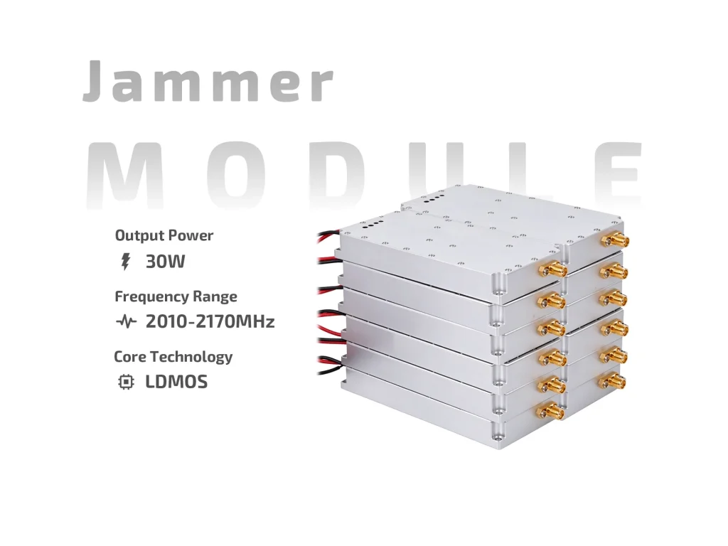
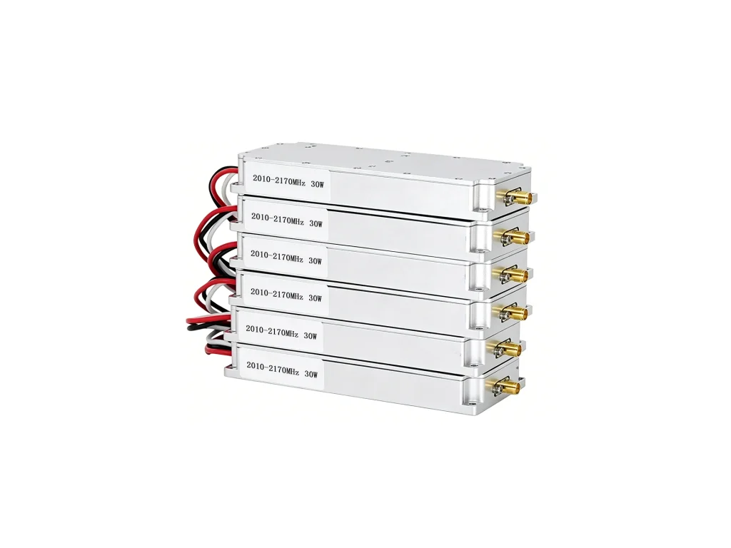
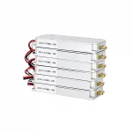
JM2021L30 30W LDMOS jamming module covers 2010-2170MHz with DC24-29V, 3.2A max, ≥40% efficiency, SMA female and built-in sweep source.
The JM2021L30 is a 30W LDMOS jamming module for the 2010–2170 MHz range. It combines an LDMOS RF amplifier, a high-speed sweep source and simple on/off control in one metal housing. The module is meant for authorized test benches, shielded rooms and controlled counter-UAV fixtures. It is not a finished outdoor transmitter. Treat it as an RF building block that needs a clean DC supply, a suitable load or antenna, and a thermal path.

The RF stage uses LDMOS devices with typical 30W output. Output VSWR is specified at ≤2.0, so the load still matters. The built-in sweep source saves an external modulator in many setups: apply power, set the switch line, and the module generates the analog sweep pattern. The SMA female output is small, so use a short, supported jumper and avoid bending the connector. A poor cable can make a stable module look noisy.
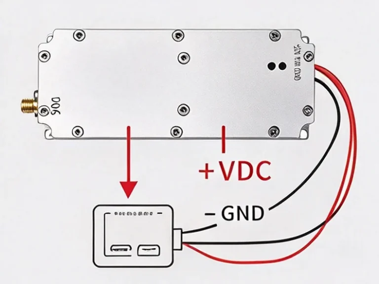
The drone jamming module runs from DC24–29V and can draw up to 3.2A. Efficiency is ≥40%, which means heat is part of the design. At 30W RF, the difference between DC input and RF output has to leave the housing. Use a supply with headroom and short leads; long thin cables drop voltage and can cause restart or drift. The switch control is straightforward: +5V or open turns it on, ground turns it off. Keep the control line away from the RF output and from switching supplies. If the line runs near noise, add a small filter or use a screened lead. Do not assume the open state is safe in every enclosure; verify it.
The case is 115.5 × 46.5 × 21 mm and weighs about 0.21 kg. It fits compact fixtures, but the small footprint does not remove the need for cooling. Mount the module on a flat metal plate with thermal compound or a pad. Run it into a dummy load for 10–15 minutes and check the plate and case rise. If the case gets hot quickly, improve the plate or add airflow. Support the SMA cable so the connector does not carry mechanical load. Keep DC and control wires on the opposite side of the RF output where possible.
Start with a dummy load and a current-limited supply. Confirm ON and OFF states before connecting an antenna. Measure output at the center and at both band edges; 30W is typical, not a guarantee at every point. Watch supply current during warm-up. A slow current rise with falling output usually points to load match or cooling. Use a power meter rated for the band and power. Record the test conditions and serial number for traceability. If the module is built into a larger assembly, repeat the check at the final connector.
Typical uses include receiver checks, shielded test cells, training rigs and controlled counter-UAV equipment. The internal sweep source makes it convenient for repeatable analog tests. For field work, add enclosure shielding, filtering, access control and the required permits. RF jamming is regulated; the integrator is responsible for frequency limits, output power and operating rules. Do not run the 30W LDMOS jamming module without a load or antenna. Do not open the case with DC applied. Use ESD-safe handling.
Confirm the 2010–2170 MHz band, SMA female output, switch polarity and expected duty cycle. Ask for a sample test report showing output, current and efficiency at room temperature. For prototypes, check the thermal design early; the RF data is only useful if the module stays within its temperature limits.
| Parameter | Specification | Notes |
| Operating Frequency | 2010–2170 MHz | Continuous band |
| Output Power | 30 W | Typical |
| Output VSWR | ≤2.0 | At output connector |
| Operating Voltage | DC24–29 V | Nominal 24 V system |
| Max. Operating Current | 3.2 A | At full output |
| Efficiency | ≥40% | DC-to-RF |
| Switch Control | +5 V or open = ON; ground = OFF | Keep control line clean |
| Output Connector | SMA female | 50 Ω |
| Jamming Source | Built-in high-speed sweep source | Analog sweep |
| Dimensions | 115.5 × 46.5 × 21 mm | L × W × H |
| Weight | 0.21 kg | Approx. |
Understand multi-band 30W drone jammer modules: band combinations, total vs per-band power, thermal trade-offs, filtering and antenna design.
Powering a 30W drone jammer module: current draw, PSU sizing, cabling, battery runtime, inrush and thermal derating tips.
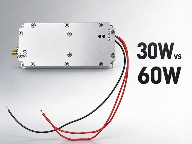
Compare 30W vs 60W drone jammer module by deployment scenario, thermal load, power budget and lifecycle cost. Choose the right tier.