October 22, 2026
What Is an 80W Jammer Module Used For?
An 80W jammer module is used in authorized counter-drone systems to disrupt specific RF links. Here is where it fits, and how to scope one.


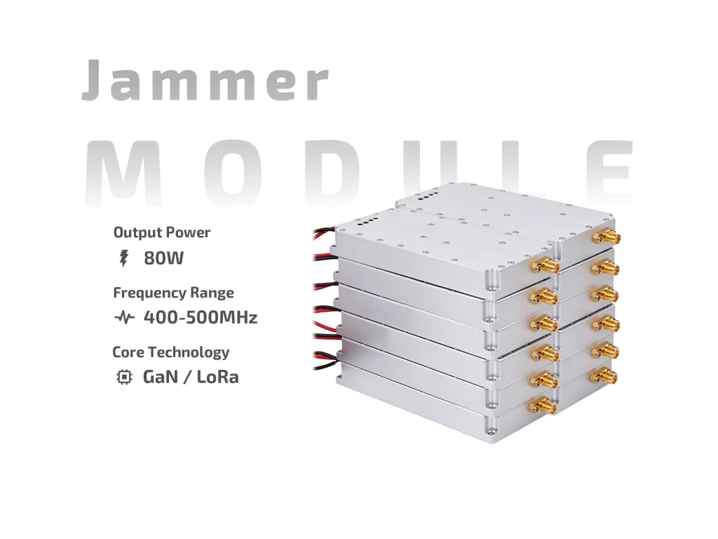
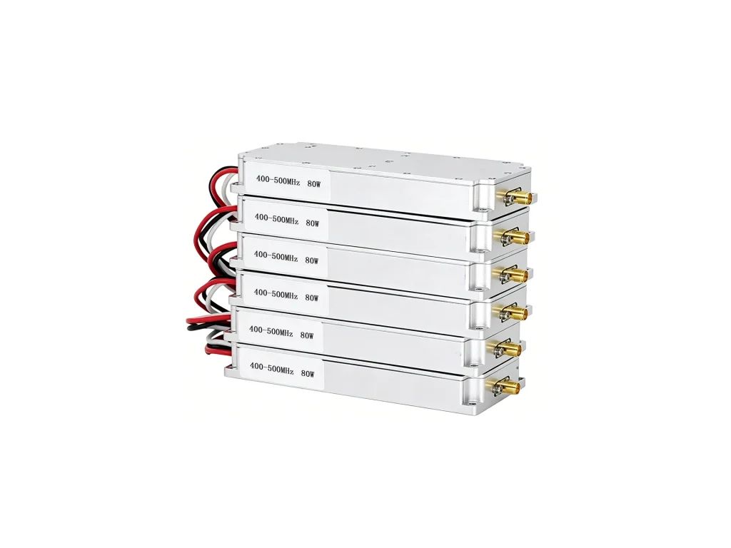
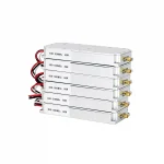
JM0405G80 80W LoRa jamming module: 400–500MHz, 24–29V DC, 10A max, ≥40% efficiency, internal sweep/VSWR protection, SMA-F, 168.5×84.5×23mm.
JM0405G80 is an 80W LoRa Jamming Module for 400–500 MHz. It is delivered as an RF building block, not a finished enclosure. The package contains a GaN output stage, a high-speed sweep source, and absorption-type VSWR protection. You supply DC, control, antenna, and cooling. That last item is not optional. The 168.5 × 84.5 × 23 mm case is compact for 80W, so the mounting surface does real work.

Run the module from a regulated 24–29V DC supply. Maximum current is 10.0A. Higher bus voltage keeps current lower for the same output, which helps cable and connector choice. Check current at 28V, then repeat near 24V. A supply that sags on sweep peaks can cause reset-like behavior that looks like an RF problem. Use short, thick leads and a clean ground return.
LoRa plans differ by country. The 400–500 MHz range covers several common low-band allocations, including 433 MHz and 470 MHz areas, plus other narrowband links. That makes JM0405G80 useful for test rigs and fixed sites where one module must cover a broad slice. It does not replace a site survey. Confirm channel use, power limits, and licensing before transmitting. The SMA female output keeps coupler and dummy-load tests simple.
The internal high-speed sweep source saves an external generator and a cable run. Treat it as a repeatable interference engine, not a lab instrument. The absorption-type VSWR protection helps when an antenna is damaged or a connector is loose. It is not a substitute for a proper load. First power-up should always be on a dummy load, with a current-limited supply and a coupler for power checks.
Switch control is +5V or floating for on, ground for off. Floating-on is convenient for remote enable, but it can catch a technician during wiring. Label the harness, and pull the enable line to ground for a safe default. Keep control wires away from the RF output. Verify the ground return before applying 24–29V. A clean enable signal prevents faults that get blamed on the RF stage.
At 0.55 kg, the 80W LoRa jamming module needs a flat metal surface, not a plastic standoff. Use thermal paste or a pad. The larger footprint gives more base area than smaller modules, but only if contact is even. Leave clearance for SMA torque and cable bend radius. In sealed boxes, derate output or add airflow. For multi-module racks, use separate DC feeds and sequence power to limit inrush.
Antenna choice matters more than many buyers expect. A 400–500 MHz antenna with gain and a clean match will outperform a wideband whip with a poor connector. Use coax rated for the band, keep runs short, and weatherproof outdoor joints. Check the match with a analyzer before connecting the module. A borrowed antenna with unknown history is a common cause of high current and unexpected heating.
Start on a dummy load. Record current, output power, and temperature rise. Sweep the band and watch for dropouts or sudden current jumps. Inspect connectors after transport. If the case runs hot, reduce duty cycle before raising output expectations. A short RF path, tight connectors, and a matched antenna solve more problems than late filtering. Keep a baseline record so later checks have a reference.
JM0405G80 suits fixed sites, vehicle mounts, and portable housings that need 400–500 MHz coverage in limited space. Pair it with DC protection, a matched antenna, and a real thermal design. For production, request a test report and confirm connector and control wiring. Do not treat 80W as a continuous guarantee in a sealed enclosure. Derate or cool it, and follow local rules.
| Parameter | Specification | Notes |
| Operating Frequency | 400–500 MHz | Covers common low-band LoRa/ISM allocations |
| Output Power | 80 W | Typical at rated supply |
| Output VSWR | ≤2.0 | Antenna match should stay within this limit |
| Operating Voltage | DC 24–29 V | Regulated supply recommended |
| Max Operating Current | 10.0 A | Size wiring and protection for continuous draw |
| Efficiency | ≥40% | Metal thermal path still required |
| Switch Control | +5 V or floating = ON | Ground = OFF |
| Output Connector | SMA female | Use quality coax and correct torque |
| Internal Sweep Source | High-speed sweep | No external generator required |
| VSWR Protection | Absorption-type device | Helps with damaged antenna or loose connector |
| Dimensions | 168.5 × 84.5 × 23 mm | Allow clearance for SMA and cables |
| Weight | 0.55 kg | Flat metal mounting surface recommended |
An 80W jammer module is used in authorized counter-drone systems to disrupt specific RF links. Here is where it fits, and how to scope one.
Comparing 80W vs 100W drone jammer module: real thermal gaps, efficiency trade-offs, bandwidth costs, and when the extra 20W is worth it.
An integration-focused review of 80W FPV jammer modules: band coverage, thermal load, power claims, field testing, and authorized use.