October 22, 2026
What Is an 80W Jammer Module Used For?
An 80W jammer module is used in authorized counter-drone systems to disrupt specific RF links. Here is where it fits, and how to scope one.


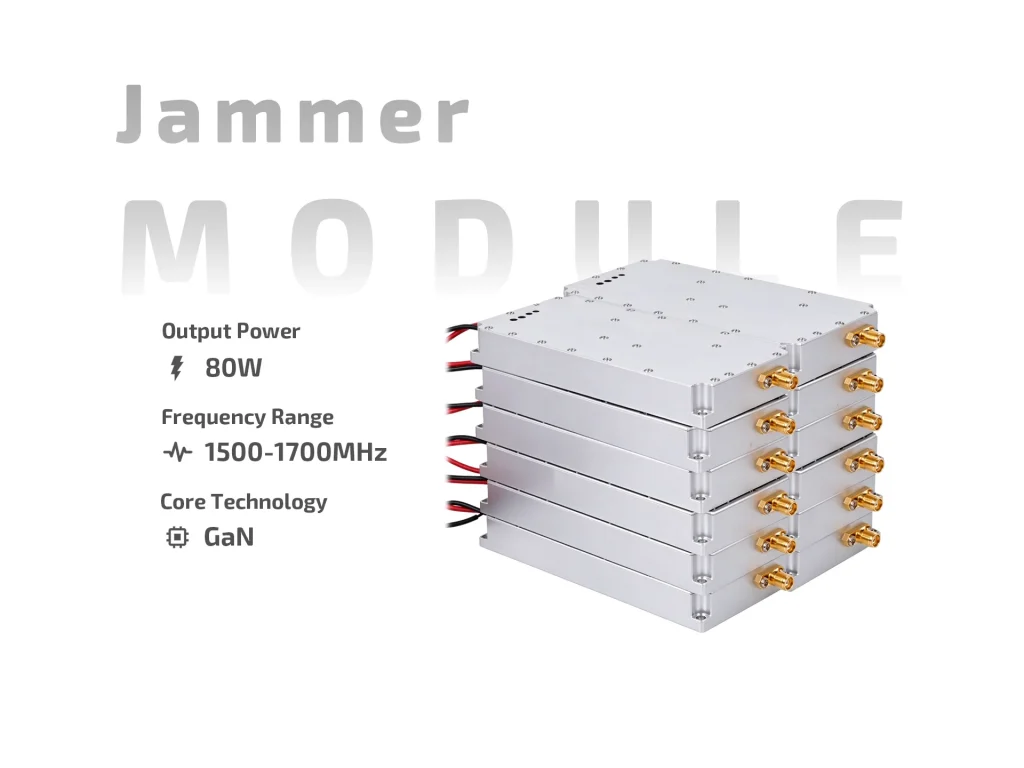
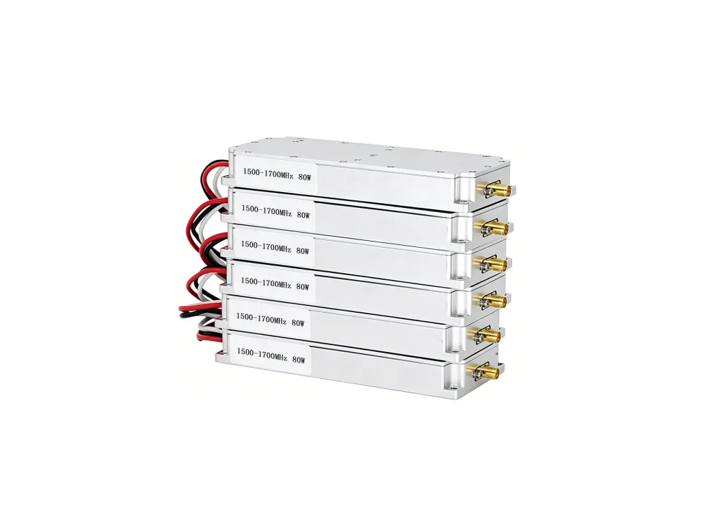
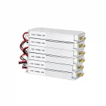
JM1517G80 80W anti-drone jammer module: 1500–1700MHz, DC24–29V, 10A max, ≥40% efficiency, SMA female, built-in sweep source and VSWR protection.
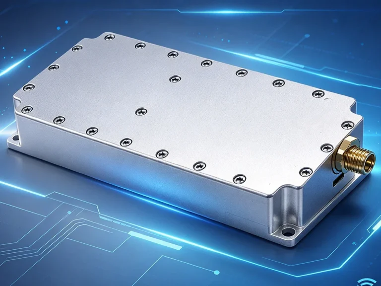
JM1517G80 is an 80W anti-drone jammer module for 1500–1700MHz work. It puts a GaN RF chain, a high-speed sweep source, and absorbed VSWR protection into one compact block. The design is for integrators who want a proven RF section, not a finished consumer unit. Power comes from DC24–29V, and the RF port is SMA female. The module is small enough for portable housings and fixed racks.

The band runs from 1500 to 1700MHz. The internal sweep source covers the range without an external controller, so host wiring stays short. GaN devices give the output stage thermal and voltage headroom at 80W. Efficiency is at least 40%. Output VSWR should stay at or below 2.0 with a matched antenna. A clean SMA female port keeps losses low on short coax runs.
Input voltage is DC24–29V. Maximum current is 10.0A. The switch pin is easy to drive: +5V or floating turns the module on; grounding turns it off. That works with relay contacts, open-collector logic, or a manual switch. Use a supply that can deliver the peak current without sag. Short, thick leads help. Add a fuse and reverse-polarity protection in the host system.
An absorbed VSWR protection part is built in. It helps during antenna mismatch, a loose connector, or a missing load. It is not a licence to run without an antenna. Keep output VSWR at 2.0 or lower in normal use. The 80W anti-drone jammer module is 168.5×84.5×23mm and weighs 0.55kg. Mount it to metal, keep air moving, and use thermal compound. Do not insulate the base.
Keep coax short and shielded. Route the antenna away from DC and control lines. Check switch polarity before the first power-up. Test into a dummy load if the antenna is not ready. The module is an RF building block; it still needs an enclosure, antenna, power source, and legal approval. Use only where drone link disruption is authorised.
Common fits include portable counter-drone packs, fixed-site RF blocks, and OEM housings for security teams. The band suits video and control links that sit in 1500–1700MHz. The 80W output gives range headroom, but antenna gain and height matter more than raw power. Buyers should match the antenna to the band and keep VSWR low.
Before deployment, check current draw at 24V and 29V. Look for heat build-up on the base. Confirm the switch line with a meter. Log output into a known load. In service, inspect connectors and coax for water or strain. Clean the mounting face and renew thermal compound if the unit is moved. A simple log helps spot drift.
Ask three questions: Is the antenna matched to 1500–1700MHz? Can the supply hold 10A? Is there airflow over the case? If any answer is no, fix it before buying more power. The JM1517G80 is a focused band module, not a multi-band box. That focus keeps filtering and matching simpler.
The footprint is 168.5×84.5×23mm. That leaves room for connectors and a small heatsink in many housings. Place the SMA port so coax does not bend sharply. Keep the case flat against metal. Use four screws and a thin thermal pad. Leave space at the ends for airflow.
Use a band-pass filter if nearby transmitters are strong. Keep the antenna away from other radios. Check the site for existing 1500–1700MHz traffic. Do not aim the antenna at people. RF exposure depends on antenna gain, distance, and duty cycle. A site survey is more useful than a power claim.
This anti-drone jammer module is not a finished jammer. It has no battery, no antenna, and no user display. It does not decide which links to target. The host system must handle mounting, cooling, power protection, and legal checks. Treat it as one RF module inside a larger product. That view keeps expectations realistic.
| Parameter | Specification | Notes |
| Frequency | 1500–1700 MHz | Single wide band for common video/control links |
| Output Power | 80 W | GaN output stage |
| Output VSWR | ≤2.0 | Keep antenna matched |
| Operating Voltage | DC24–29 V | Regulated supply recommended |
| Max Current | 10.0 A | Allow headroom in wiring and fuse |
| Efficiency | ≥40% | Thermal design still required |
| Switch Control | +5V or floating = ON; ground = OFF | Simple logic or relay control |
| Output Connector | SMA female | Short shielded coax |
| Interference Source | Built-in high-speed sweep source | No external sweep controller |
| VSWR Protection | Built-in absorbed VSWR protection | Helps with mismatch; not a substitute for a load |
| Dimensions | 168.5×84.5×23 mm | Mount on metal |
| Weight | 0.55 kg | Check housing support |
An 80W jammer module is used in authorized counter-drone systems to disrupt specific RF links. Here is where it fits, and how to scope one.
Comparing 80W vs 100W drone jammer module: real thermal gaps, efficiency trade-offs, bandwidth costs, and when the extra 20W is worth it.
An integration-focused review of 80W FPV jammer modules: band coverage, thermal load, power claims, field testing, and authorized use.